Hardware Overview
The pinout
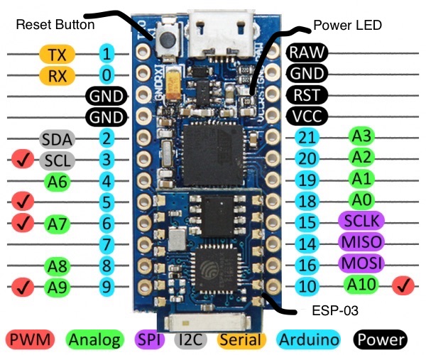
Here’s a map of which pin is where, and what special hardware functions it may have:
Power Pins
There are a variety of power and power-related nets broken out:
- RAW is the unregulated voltage input for the Cactus Micro. If the board is powered via USB, the voltage at this pin will be about 4.8V (USB’s 5V minus a schottkey diode drop). On the other hand, if the board is powered externally, through this pin, the applied voltage can be up to 9V.
- VCC is the voltage supplied to the on-board ATmega32U4. It’ll be either 3.3V. This voltage is regulated by the voltage applied to the RAW pin. If the board is powered through the ‘RAW’ pin (or USB), this pin can be used as an output to supply other devices.
- RST can be used to restart the Cactus Micro. This pin is pulled high by a 10k&Ohm; resistor on the board, and is active-low, so it must be connected to ground to initiate a reset. The Cactus Micro will remain “off” until the reset line is pulled back to high.
- GND, is the common, ground voltage (0V reference) for the system.
I/O Pins
The Cactus Micro’s I/O pins – 18 in all – are multi-talented. Every pin can be used as a digital input or output, for blinking LEDs or reading button presses. These pins are referenced in the Arduino IDE via an integer value between 0 and 21. (The A0-A3 pins can be referenced digitally using either their analog or digital pin number).
Nine pins feature analog to digital converters (ADCs) and can be used as analog inputs. These are useful for reading potentiometers or other analog devices using the analogRead([pin]) function.
There are five pins with pulse width modulation (PWM) functionality, which allows for a form of analog output using the analogWrite([pin], [value]) function. These pins are indicated on-board with a faint, white circle around them.
There are hardware UART (serial), I2C, and SPI pins available as well. These can be used to interface with digital devices like serial LCDs, XBees, IMUs, and other serial sensors.
The Cactus Micro has five external interrupts, which allow you to instantly trigger a function when a pin goes either high or low (or both). If you attach an interrupt to an interrupt-enabled pin, you’ll need to know the specific interrupt that pin triggers: pin 3 maps to interrupt 0, pin 2 is interrupt 1, pin 0 is interrupt 2, pin 1 is interrupt 3, and pin 7 is interrupt 4.
ESP8266 Pins
The Cactus Micro Rev2 has connected to esp8266 with these pins.
| ESP8266 | Cactus Micro Rev2 |
| GPIO0 | 12 |
| ENABLE (CH_PD) | 13 |
| RX | TXO (Serial1) |
| TX | RXI (Serial1) |
| GND | GND |
| GPIO13 | 2 (For I2C etc) |
| GPIO12 | 3 (For I2C etc) |
| GPIO14 | A4 |
On-Board LEDs
There's one red LED indicates whether power is present.
How to Power Cactus Micro Rev2
As the Cactus Micro’s main feature is its innate USB functionality, the most common way to power it is via USB. In this setup, a Cactus Micro will regulate the 5V supply coming in from USB down. The other end of the USB cable can be connected to either a computer, USB hub, or a USB wall adapter, which can (in most cases) provide more power.
Alternatively, if your Cactus Micro is living out in the wild, out of reach of USB cables, it can be powered through either the ‘RAW’ or ‘VCC’ pins. A supply going into the ‘RAW’ pin will be regulated down to the correct operating voltage (3.3V). To be safe, it shouldn’t be any higher than 9V, and it should be at least 1V more than the Cactus Micro’s operating voltage (e.g. > 4.3V).
If you power the Cactus Micro through the ‘VCC’ pin, keep in mind that this signal is unregulated. Only use this if you have a clean, regulated 3.3V supply to connect to it.